

SA504 220V AC Modulating with Analog 0-10V DC Signal
SA504 is a 220V AC modulating connection for motorized valves, controlled by a 0–10V DC analog input signal. This wiring model has no feedback function.
Wiring Diagram
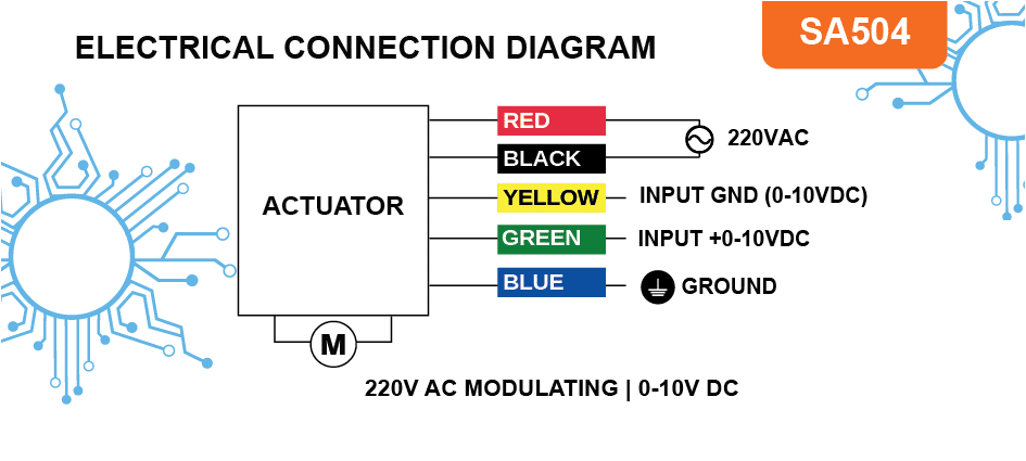
Wire Connections
Disconnect power before making or changing connections.
- Connect 220V AC phase to the red wire.
- Connect 220V AC neutral to the black wire.
- Connect the green wire to the positive (+) 0–10V DC signal terminal.
- Connect the yellow wire to the negative (−) 0–10V DC signal terminal.
- Keep the 220V AC supply connected during normal operation.
- Connect the blue wire to ground/earth for safety.
How to Connect an Analog Input Signal
The analog input controls the valve position. A suitable 0–10V DC signal may come from a pressure sensor, temperature sensor, flow sensor or level transmitter.
If the sensor output needs conversion or adjustment, use an appropriate controller. For example, an RTD temperature probe can connect to a temperature controller that converts the probe input into a 0–10V DC output based on the configured low and high temperature setpoints. This output can then control the modulating valve.
Safety: Follow the relevant electrical safety guidelines. Consult a qualified electrician if you are unsure about connecting the actuator or any other electrical device.