

SA603 12V DC Modulating 4-20mA with Analog Output 4-20mA
SA603 is a 12V DC modulating circuit for motorized valves. It uses a 4–20mA analog input signal and provides a 4–20mA feedback output.
Wiring Diagram
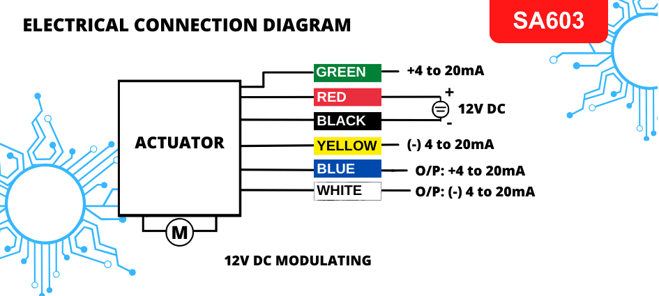
Supply and Input Connections
Disconnect power before making or changing connections.
- Connect the black wire to the negative terminal of the 12V DC power source.
- Connect the red wire to the positive terminal of the 12V DC power source.
- Keep these two supply wires permanently connected during normal operation.
- Connect the green wire to the positive (+) terminal of the 4–20mA signal source.
- Connect the yellow wire to the negative (−) terminal of the 4–20mA signal source.
Feedback Output Connections
- Blue wire: Positive (+) 4–20mA feedback output.
- White wire: Negative (−) 4–20mA feedback output.